
Shu Guang
A J Slotted Fuse is a compact overcurrent protection device designed to interrupt dangerous current before wiring or equipment suffers serious damage. Its slotted terminal design supports firm installation inside compatible fuse holders. The slot also helps distinguish this fuse from other blade or cartridge formats.
Electrical safety educator Mike Holt states, “Overcurrent protection must be matched to the conductor.” This principle explains why fuse selection requires more than comparing ampere ratings. Engineers must check voltage, interrupting capacity, time-current behavior, holder compatibility, and the protected wire’s allowable load. A correct J Slotted Fuse should open safely during a fault, not merely fit the socket.
The operating process is simple but carefully controlled. Under normal conditions, current passes through a calibrated fusible element. That element remains cool enough to carry the expected load. During a short circuit or sustained overload, resistance produces heat. The element melts. The circuit opens.
Fast action matters.
Inside the fuse body, insulating material helps contain the arc created during interruption. Some designs use filler material to absorb energy and limit flame or metal spray. The result is a cleaner disconnection, especially when fault current rises sharply.
This guide will examine the fuse’s construction, ratings, installation requirements, and practical applications. It will also compare J Slotted Fuse designs with similar protection devices. Small mistakes remain possible. A fuse can look correct while its voltage rating, interrupting capacity, or holder is unsuitable. That detail deserves careful checking before energizing any circuit.
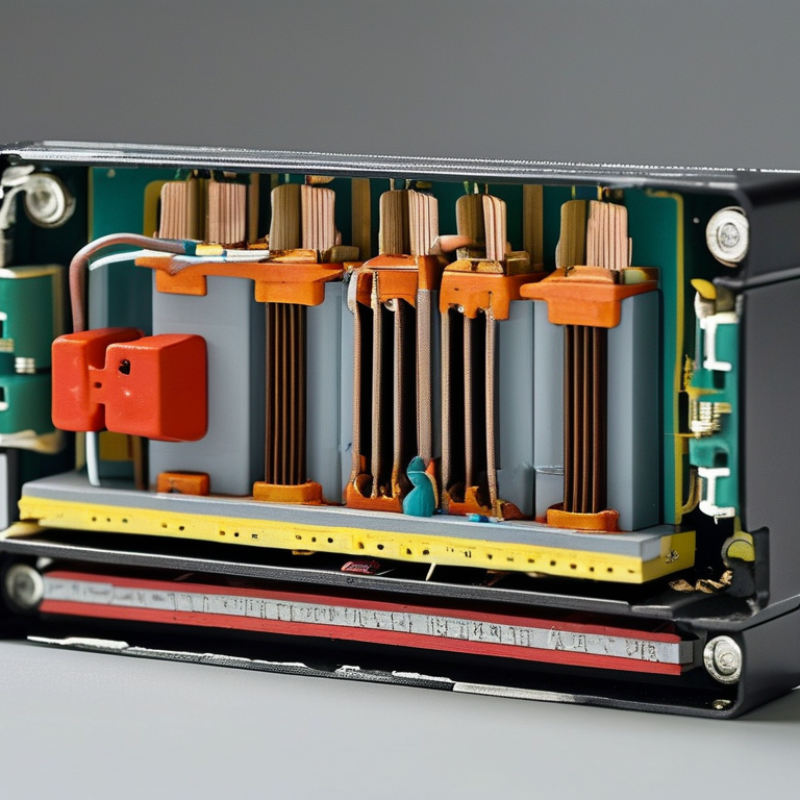
A J-slotted fuse is a compact current-limiting fuse built to Class J dimensions and performance requirements. Under UL 248, Class J fuses are generally rated for systems up to 600 V AC. Some listed designs provide an interrupting rating up to 200 kAIC, meaning they can safely interrupt very high available fault currents when correctly applied.
The “J-slot” feature helps match the fuse with a compatible holder. Its rejection geometry discourages installation of a fuse from another class with different electrical limits. Inside the body, a calibrated element melts when current exceeds its time-current characteristic. Silica-based filler absorbs heat and helps extinguish the arc. Fast-acting versions protect sensitive equipment, while time-delay versions tolerate brief motor-starting surges.
In panel inspections, the label deserves careful attention. A 600 V rating alone does not confirm suitability. Check the available fault current, conductor size, ambient temperature, load type, and whether the circuit is AC or DC. The 200 kAIC figure is not universal for every Class J fuse; it applies only to properly tested and marked products. This detail is easy to miss. So is the holder rating. Replacing a fuse by physical fit alone is poor practice, even when the dimensions appear identical. A qualified technician should verify the complete protection scheme against current installation requirements.
Class J fuses are current-limiting fuses standardized for circuits up to 600 V AC, with interrupting ratings commonly reaching 200 kA RMS symmetrical.
The chart shows representative Class J ampere ratings from the standardized 1–600 A range. During a short circuit, the fuse element melts rapidly and the filler material helps extinguish the arc, limiting fault current before it reaches its prospective peak. The 600 V and 200 kA interrupting figures describe the maximum circuit voltage and available fault current the fuse rating is designed to interrupt under applicable test conditions.
A J slotted fuse protects a circuit by interrupting current when heat rises beyond a safe level. Its internal structure is more deliberate than its compact body suggests. The slotted link guides how current travels through the fuse. These openings also reduce metal mass around selected sections, creating controlled thermal points.
The fuse element is the calibrated conductor inside the link. During normal operation, it carries current with limited temperature rise. Under overload, resistance converts electrical energy into heat. The narrow element then melts and separates the circuit. This action must occur predictably, not merely quickly. Small changes in width, thickness, or alloy can alter the operating curve.
The housing surrounds the link with an insulating, heat-resistant material. It helps contain hot particles and supports the terminals during installation. Heat also moves through the terminal blades and mounting area. Good heat paths prevent unnecessary stress on nearby wiring and reduce temperature buildup inside the body. A practical inspection should check discoloration, looseness, and melted plastic. However, appearance alone cannot confirm a fuse’s rating. The J-shaped slot may look simple, but its dimensions reflect careful engineering. In real applications, contact resistance and ambient temperature can still change performance. That is an imperfect detail worth remembering.
A J-slotted fuse uses a calibrated element to limit dangerous fault current. Its slot geometry supports secure installation and consistent heat transfer. The key process is I²t heating, not simply high current. When current rises, heat increases with the square of current. A 100 A fuse carrying 1,000 A produces roughly 100 times its rated heating effect. Even a short fault can become destructive.
The element begins melting at its weakest section. This stage is called pre-arcing. The energy released before melting is the pre-arcing I²t value. After separation, an arc bridges the gap. Internal filler material absorbs energy and helps extinguish that arc. The complete interruption value is total clearing I²t. IEC 60269-1:2024 evaluates these time-current and breaking-performance characteristics. UL 248-1 listings commonly show Class J fuses with interrupting ratings near 200 kA, depending on the construction and certification. These figures are not interchangeable. A practical mistake is comparing only ampere ratings.
Tips: Check both pre-arcing and total clearing I²t. Confirm the voltage, frequency, interrupt rating, and conductor size. A fuse that fits physically may still be electrically unsuitable. Use manufacturer test curves, but question assumptions. Cable temperature, enclosure airflow, and repeated faults can change performance. The calculation is useful, though never perfect. A slightly overlooked installation detail may matter.
A J-slotted fuse uses a shaped internal element to control heat concentration and interruption. The slot is not decorative. It influences current density, melting location, and arc separation inside the fuse body. In field testing, technicians should compare the fuse’s time-current curve with measured inrush current, not rely only on its ampere rating.
At 500% of rated current, or 5 × In, the difference between fast-acting and time-delay performance becomes clear. Fast-acting designs commonly interrupt within tens of milliseconds, limiting downstream fault energy. Time-delay designs may conduct for hundreds of milliseconds or several seconds, depending on construction and rated size. Published curves and test methods under IEC 60269-1 and UL 248-1 show that no universal clearing time exists at 5 × In. Ambient temperature, installation, and preheating also shift the result. Small details matter.
The key engineering value is I²t. At the same fault current, doubling clearing time approximately doubles let-through energy. That can damage sensitive conductors or semiconductor equipment. A time-delay J-slotted fuse may tolerate motor-start surges, while a fast-acting version offers better short-circuit limitation. This trade-off is easy to underestimate. Engineers should verify both pre-arcing and total clearing times from certified test data. Real circuits are less tidy than laboratory curves.
A J-slotted fuse is a current-limiting fuse with rejection slots in its body. These slots help prevent installation in an incompatible fuse holder. During a short circuit, the fuse element melts rapidly. Internal filler material then limits fault energy and reduces equipment damage.
Ampere rating must match the circuit design, not simply the load nameplate. Check the continuous load, motor starting current, and allowable conductor ampacity. The fuse voltage rating must meet or exceed the system voltage. A lower rating can create unsafe interruption conditions. It is easy to overlook phase-to-phase voltage in a multi-phase panel.
SCCR is another critical selection point. Confirm the fuse interrupting rating against the available fault current at the installation point. The complete assembly also needs an adequate short-circuit current rating. Conductor coordination requires matching overcurrent protection with conductor size, insulation temperature, and installation conditions. Follow the applicable electrical code and equipment standard, such as NEC or relevant IEC requirements. A properly rated fuse may still be unsuitable if the conductors are undersized or poorly coordinated. Field markings can be unclear. Recheck the panel schedule, fuse class, and holder rating before energizing the circuit. This extra review feels slow, but it prevents expensive assumptions.
| Selection Factor | Typical Data | What It Means | Selection and Coordination Check | Applicable Reference |
|---|---|---|---|---|
| Fuse construction | Current-limiting, blade-type fuse with slotted mounting terminals | The slotted terminal provides a mechanical mounting interface; the fuse element opens the circuit during an overcurrent event. | Confirm that the fuse, clips or blocks, and conductors are mechanically compatible and rated for the same system voltage and current. | UL 248-8, Class J fuse requirements |
| Ampere rating | Common Class J ratings range from approximately 1 A to 600 A | The ampere rating is the continuous current the fuse is intended to carry under specified conditions. | Select a rating based on the calculated load current, motor or transformer inrush, ambient temperature, and the applicable overcurrent-protection rules. | NEC 210.20, 215.3, 240.4 and equipment instructions |
| Voltage rating | Typically up to 600 V AC for Class J applications; some products also carry a separate DC rating | The fuse voltage rating must be equal to or greater than the circuit voltage. AC and DC ratings are not automatically interchangeable. | Check the marking for system voltage, frequency, AC/DC suitability, and the required pole or phase arrangement. | UL 248-8 and the fuse marking |
| Interrupting rating | Many Class J fuses are marked 100 kA or 200 kA RMS symmetrical at rated AC voltage | This is the maximum prospective short-circuit current the fuse is rated to interrupt safely at the specified voltage. | Never assume a standard value. Use the exact marked interrupting rating and ensure it is at least equal to the available fault current at the installation point. | NEC 110.9; UL 248-8; available fault-current study |
| SCCR of the assembly | The final SCCR is limited by the lowest-rated component or tested combination | A high-interrupting-rating fuse does not automatically give the complete panel or equipment the same SCCR. | Verify fuse class, fuse holder, busbar, terminals, disconnect, enclosure, and any tested series combination as a complete system. | NEC 110.10; UL 508A Supplement SB where applicable |
| Conductor ampacity | Conductor ampacity should generally be at least equal to the fuse rating | The conductor must be protected from overheating under normal load and overload conditions. | Apply conductor size, insulation temperature, ambient correction, bundling adjustment, terminal temperature limits, and installation method before selecting the fuse. | NEC 110.14(C), 310.16 and 240.4 |
| Small-conductor limitation | 14 AWG copper is generally limited to 15 A; 12 AWG copper to 20 A; 10 AWG copper to 30 A, subject to code conditions | The general ampacity table does not override specific small-conductor overcurrent limits. | Do not select a larger fuse solely because the conductor’s table ampacity appears higher. Check the small-conductor rules and equipment terminals. | NEC 240.4(D) |
| Continuous load | Continuous load is generally calculated at 125% before final overcurrent-device selection | A continuous load operates for three hours or more under normal conditions. | Calculate the noncontinuous load plus 125% of the continuous load, then select a standard fuse rating that does not exceed the permitted conductor protection. | NEC 210.20(A), 215.2(A)(1) and 215.3 |
| Motor and transformer loads | Fuse rating may need to exceed running current to withstand permitted inrush | Starting current and magnetizing inrush can be much higher than normal operating current. | Use the applicable motor or transformer rules, manufacturer time-current curves, and conductor ampacity. A fuse must protect the circuit without nuisance opening during normal starting. | NEC Articles 430 and 450; equipment instructions |
| Selective coordination | Requires time-current curves or tested data for the upstream and downstream protective devices | Selective coordination allows the protective device nearest the fault to open before an upstream device opens. | Compare published total-clearing and peak-let-through data. Ampere ratios alone do not prove selective coordination. | NEC 700.32, 701.27 and 708.54 where applicable |
| Physical compatibility | Class J dimensions and terminal arrangements must match the holder or switch | A fuse with the correct electrical rating may still be unsafe or unusable if it does not fit the approved mounting hardware. | Confirm fuse class, dimensions, blade spacing, terminal style, torque requirements, touch-safe features, and enclosure clearances. | UL 248-8, installation instructions and equipment listing |
| Important: The values shown are representative selection data, not a substitute for the exact fuse marking, manufacturer time-current information, equipment listing, available-fault-current calculation, or the electrical code enforced at the installation location. | ||||
: It is a current-limiting fuse with shaped slots in its body. Slots matter. They support correct holder matching and influence internal heat transfer.
Heat rises with the square of current. A 100-ampere fuse carrying 1,000 amperes experiences roughly 100 times its rated heating effect. The element melts at its weakest section, stopping current flow.
Pre-arcing I²t is the energy released before the fuse element separates. It describes the melting stage. It does not represent the complete interruption process.
Total clearing I²t includes pre-arcing energy and the following arc energy. After melting, an arc briefly crosses the gap. Internal filler helps absorb energy and extinguish it.
Fast-acting designs may interrupt within tens of milliseconds. Time-delay designs may conduct for hundreds of milliseconds or several seconds. The better choice depends on fault protection and starting current.
At 500% of rated current, timing differences become significant. A fast fuse can limit downstream energy quickly. A time-delay fuse may tolerate motor-start surges.
Check ampere rating, voltage rating, interrupting rating, and available fault current. Also verify conductor size, insulation temperature, holder compatibility, and assembly short-circuit rating. Physical fit proves very little.
Compare both pre-arcing and total clearing I²t values. Review certified time-current curves against measured inrush current. Doubling clearing time approximately doubles let-through energy at the same current.
Yes. Ambient temperature, enclosure airflow, cable heating, and repeated faults can shift performance. A clean laboratory curve may not match a crowded panel. That assumption fails. Recheck field markings and connection details before energizing the circuit.
A J Slotted Fuse is a Class J current-limiting fuse designed for systems rated up to 600 volts, with interrupting capacities reaching 200 kAIC under applicable UL 248 requirements. Its internal construction typically includes slotted fuse links, a calibrated fuse element, an insulating housing, and controlled heat-transfer paths. These features help manage thermal energy and safely contain the effects of a fault.
During an overcurrent event, heat generated according to the I²t relationship raises the element’s temperature until it melts. The resulting arc is controlled and extinguished within the fuse body, interrupting current and limiting let-through energy. Fast-acting versions respond quickly to short circuits, while time-delay designs tolerate temporary inrush currents and operate more slowly at approximately 500% of their rated current. Selecting the correct fuse requires matching its ampere and voltage ratings, confirming the system short-circuit current rating, and coordinating it with conductors and protective devices according to applicable installation standards.